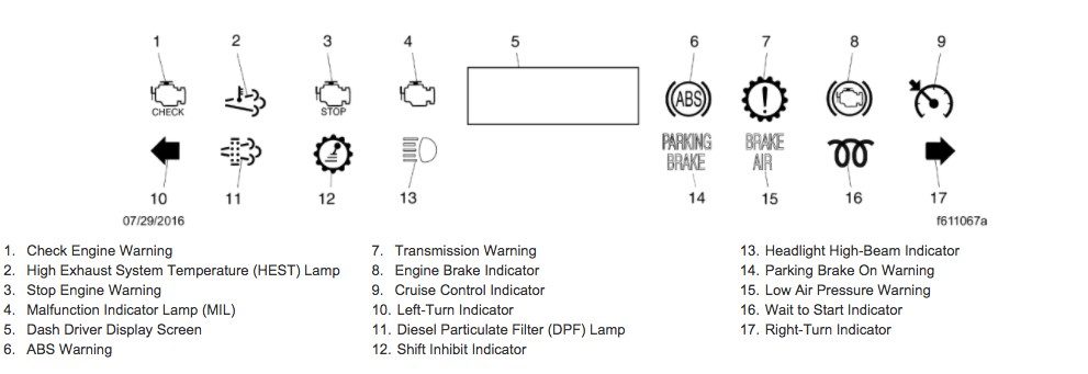
The Freightliner dash warning lights and symbols are part of the Instrumentation Control Unit (ICU3S), and Ametek instrument panels are in vehicles equipped with various warning and indicator lamps. These are detailed in Fig. 6.1 for the ICU3S panel and Fig. 6.2 for the Ametek panel. The instrument cluster includes an emergency buzzer that alerts the driver to serious conditions requiring immediate attention.
Below is an alphabetical list describing the standard warning and indicator lamps found in these panels, applicable to each type of instrument panel as relevant.
💥See also: Ecu 128 Code On Freightliner
List Of Freightliner Truck Dash Warning Lights and Symbols
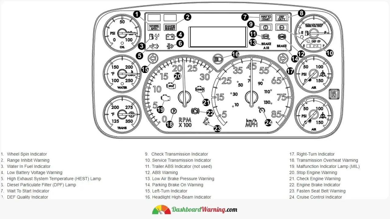
Symbols in Figure 6.1 and their meanings:
- 1. Wheel Spin Indicator
- 2. Range Inhibit Warning
- 3. Water In Fuel Indicator
- 4. Low Battery Voltage Warning
- 5. High Exhaust System Temperature (HEST) Lamp
- 6. Diesel Particulate Filter (DPF) Lamp
- 7. Wait To Start Indicator
- 8. DEF Quality Indicator
- 9. Check Transmission Indicator
- 10. Service Transmission Indicator
- 11. Trailer ABS Indicator (not used)
- 12. ABS Warning
- 13. Low Air Brake Pressure Warning
- 14. Parking Brake On Warning
- 15. Left-Turn Indicator
- 16. Headlight High-Beam Indicator
- 17. Right-Turn Indicator
- 18. Transmission Overheat Warning
- 19. Malfunction Indicator Lamp (MIL)
- 20. Stop Engine Warning
- 21. Check Engine Warning
- 22. Engine Brake Indicator
- 23. Fasten Seat Belt Warning
- 24. Cruise Control Indicator
Symbols in Figure 6.2 and their meanings:
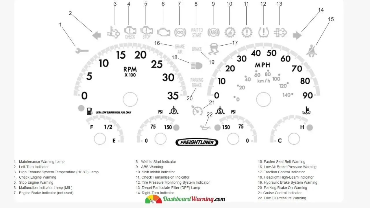
- 1. Maintenance Warning Lamp
- 2. Left-Turn Indicator
- 3. High Exhaust System Temperature (HEST) Lamp
- 4. Check Engine Warning
- 5. Stop Engine Warning
- 6. Malfunction Indicator Lamp (MIL)
- 7. Engine Brake Indicator (not used)
- 8. Wait to Start the Indicator
- 9. ABS Warning
- 10. Shift Inhibit Indicator
- 11. Check Transmission Indicator
- 12. Tire Pressure Monitoring System Indicator
- 13. Diesel Particulate Filter (DPF) Lamp
- 14. Right-Turn Indicator
- 15. Fasten Seat Belt Warning
- 16. Low Air Brake Pressure Warning
- 17. Traction Control Indicator
- 18. Headlight High-Beam Indicator
- 19. Hydraulic Brake System Warning
- 20. Parking Brake On Warning
- 21. Cruise Control Indicator
- 22. Low Oil Pressure Warning
Detailed Explanations of Freightliner Instrument Symbols
ABS Warning Light
The ABS warning light comes on if there's a problem with the vehicle's anti-lock braking system. For further details about this light and the ABS, refer to Chapter 12.
Engine Check Warning
This warning light turns on due to specific faults, particularly critical issues like low oil pressure or high coolant temperature. It prompts the driver to address these issues promptly. Should the situation worsen, the stop engine light will also turn on.
Important: Seek immediate service at an authorized Thomas Built Bus facility if this light activates while driving.
Transmission Check Indicator
Note: This indicator is relevant for both ICU3S and Ametek panels.
In LPG vehicles with an Ametek panel, the transmission check light activates when the transmission fluid's temperature exceeds the manufacturer's specified level. Consult the transmission manufacturer's manual for more details.
Note: This light may also indicate a transmission fault. Check the transmission manufacturer's manual for further information.
The transmission check light alerts the driver about the oil life monitor, filter life monitor, and transmission health monitor statuses, indicating when maintenance is needed. Consult the Allison Operator's Manual or contact Allison Transmission customer support to identify the specific issue triggering the light.
Cruise Control Indicator
This light indicates that the cruise control feature is active.
DEF Quality Indicator
Activates to signal that the Diesel Exhaust Fluid (DEF) concentration is diluted or contaminated.
Diesel Particulate Filter (DPF) Light
A steady light signals the need for regeneration, which can be achieved through intense driving, like highway driving for at least 20 minutes or stationary regeneration. Refer to the engine operation manual for details.
A blinking light indicates an immediate need for stationary regeneration, failing which engine derate and shutdown may occur. Follow the engine manufacturer's manual for proper fixed regeneration instructions.
Emergency Buzzer
The emergency buzzer sounds during ignition and under these conditions:
- If the engine oil pressure drops below the manufacturer's specified level.
- When the coolant temperature exceeds the threshold of 225°F (107°C).
- If the air pressure is below 65 psi (448 kPa).
- When the parking brake is engaged while the vehicle moves faster than 2 mph (3 km/h).
Engine Brake Indicator
This light indicates the activation of the engine brake.
Seat Belt Warning
The seat belt warning light (represented by a seat belt icon) stays lit for 3 seconds after turning on the ignition. If the driver's seat belt is not fastened while the engine runs and the parking brake is not set, the warning light comes on, and a chime sounds for 10 seconds. The light stays on until the seat belt is fastened.
High-Beam Headlight Indicator
The high-beam indicator, marked with a sideways beam icon, lights up when the vehicle's high beams are activated.
High Coolant Temperature Alert
The high coolant temperature warning, represented by a thermometer icon and an emergency buzzer, signals when the coolant temperature exceeds the engine manufacturer's set maximum. For additional information, refer to the engine manufacturer's manual.
High Exhaust System Temperature (HEST) Indicator
A slow 10-second flash of this indicator means regeneration is underway without driver control over engine idle speed. A steady light warns of high exhaust temperatures at the tailpipe outlet if the vehicle's speed is under 5 mph (8 km/h). This doesn't require service but alerts the driver to elevated exhaust temperatures. Refer to the engine operation manual for more details.
Hydraulic Brake System Warning (Propane Engine Only)
This warning light signifies a hydraulic brake system failure or if the vehicle is on while the engine is off.
Left-Turn Signal Indicator
This indicator blinks in sync with the left-turn signal lights. When the hazard warning is engaged, both turn signal indicators flash.
Low Air Brake Pressure Alert
When the air pressure in the primary or secondary air reservoir falls below 65 to 75 psi (448 to 517 kPa), the low air brake pressure warning indicator and emergency buzzer activate. They remain on until the pressure exceeds that level in both reservoirs.
Low Battery Voltage Indicator
The low battery voltage warning, indicated by a battery icon, lights up when the voltage falls below 12 volts.
Low Oil Pressure Alert
The low oil pressure warning is shown with an oil can icon, and an emergency buzzer is activated when the engine oil pressure drops below the manufacturer's specified minimum. Consult the engine manufacturer's manual for more details.
Maintenance Warning Light (Propane Engine Only)
This lamp alerts the driver with the following messages on the display center:
- Oil Change Required: The engine has reached the recommended oil change interval.
- Air Filter Reminder: Signals the need to check or replace the air filter.
- Transmission Prognostics Warning: This appears if the transmission has prognostics enabled.
Malfunction Indicator Lamp (MIL)
This lamp indicates an engine emissions-related fault, which may include issues with the after-treatment system. For more information, refer to the engine operation manual.
Parking Brake Engagement Warning
This indicator lights up when the parking brake is engaged. If the vehicle moves at 2 mph (3 km/h) or faster, the emergency buzzer sounds until the parking brake is released.
Range Inhibit/Shift Inhibit Indicator
Note: This indicator doesn't appear on the instrument panel in vehicles equipped with an Allison 3000 transmission. It's displayed on the transmission push-button shifter screen.
The range inhibits (ICU3S panel), or shift inhibit (Ametek panel) indicator lights up when conditions for safe transmission shifting aren't met.
Right-Turn Signal Indicator
This indicator flashes in tandem with the right-turn signal lights. Both turn signal indicators flash when the hazard warning flasher is on.
Service Transmission Alert
Note: This indicator is absent in the instrument panel of vehicles with an Allison 3000 transmission; instead, it appears on the transmission push-button shifter display screen.
The service transmission indicator signals the need for transmission maintenance, such as oil or filter changes. When this light comes on, consult the Allison Operator's Manual or contact Allison Transmission customer support for specific troubleshooting.
Stop Engine Warning
The stop engine warning light indicates the activation of the engine's protection system. Sometimes, the engine's electronic control unit (ECU) will reduce its power, allowing it to run at lower RPMs and speed. Under these conditions, the vehicle can be driven to a safe location.
The engine ECU reduces the engine's power. Drivers should safely pull over to the roadside.
Notice: When the stop engine indicator illuminates, promptly move the vehicle to a safe location to prevent severe engine damage. To restart the engine, turn the ignition switch to OFF, wait a few seconds, and then turn it to START.
Important: Avoid restarting the engine while the vehicle is in motion. Bring the car to a complete stop before resuming.
Tire Pressure Monitoring System (TPMS) Indicator

The TPMS indicator lights up when a tire issue is detected, such as underinflation, overinflation, or overheating. A warning message also appears on the driver display screen. Refer to Fig. 6.3 for details.
Traction Control Indicator
This indicator lights up when the vehicle's wheels lose traction.
Transmission Overheat Warning
The transmission overheat warning (ICU3S panel) activates when the transmission fluid temperature exceeds the manufacturer's specified limit. Refer to the transmission manufacturer's manual for more details.
Water in Fuel Alert
The water in the fuel indicator alerts when water is detected in the fuel tank.
Notice: Water in the fuel/water separator appears as beads. With the engine off, drain only enough to remove the water (about two teaspoons at a time). Avoid completely draining the separator to prevent the need to prim the fuel system before starting the vehicle.
Warning: Diesel fuel is flammable and can ignite if exposed to open flames or intense heat. Avoid draining fuel near any ignition sources. When handling the fuel system, keep a fire extinguisher within reach.
Drain any accumulated water from the fuel/water separator.
Wheel Spin Indicator
This indicator lights up when a wheel spin event occurs, and the automatic traction control (ATC) system is engaged.
Optional Indicator Lights
Optional lights include an intake heater, low brake fluid, low coolant, low fuel, automatic transmission range inhibit, pall filter, differential lock, and wheel spin indicators.
Air Filter Indicator
The air filter indicator (marked "AIR FILTER") lights up when the air cleaner filter element is significantly clogged, reducing intake airflow below 25 inH2O. If this indicator stays lit, check the air intake restriction gauge, replace the air filter if necessary, and reset the indicator. Importantly, never attempt to clean the air filter.
Alternator No Charge Indicator
The alternator no charge indicator (marked "NO CHARGE") activates when the alternator fails to charge correctly.
Electronic Stability Control (ESC) Indicator

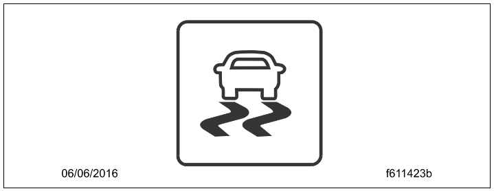
The ESC indicator, shown in Fig. 6.4 for the ICU3S panel and Fig. 6.5 for the Ametek panel, lights up when the ESC system is in action.
Wait to Start Indicator

Note: Despite being among optional indicators, the wait-to-start indicator is standard.
This indicator (see Fig. 6.6) comes on with the ignition switch in the ON position before starting the engine. Wait for this indicator to turn off before cranking the engine to avoid triggering a fault code.
Speedometer and Tachometer
Speedometer
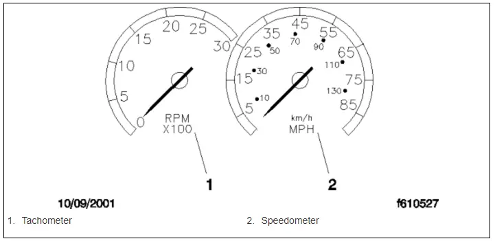
Three speedometer versions are available. The U.S. version displays mph and km/h speed, with mph more prominently displayed. See Fig. 6.7. The NAFTA version shows km/h more prominently, and the metric-only version shows only km/h.
Tachometer
The tachometer measures engine speed in RPM, aiding in transmission shifting and maintaining optimal engine RPM. Refer to Fig. 6.7.
Standard Gauges
Engine Oil Pressure Gauge
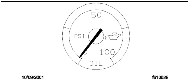
Notice: A sudden drop in oil pressure may indicate a mechanical issue. Stop the vehicle safely and investigate the cause to prevent damage. Wait to run the engine until the problem is resolved. Suppose oil pressure falls below a certain level. In that case, the check engine light and possibly the stop engine light will illuminate, and a buzzer will sound. The engine may derate or shut down depending on the protection system. See Fig. 6.8 for the gauge.
Coolant Temperature Gauge
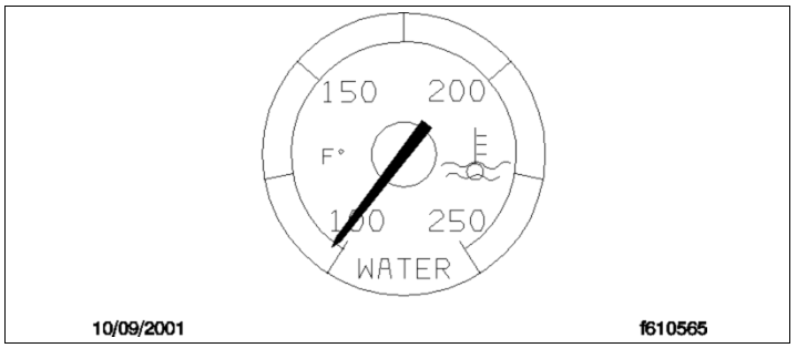
Notice: A rapid increase in coolant temperature may signal engine or cooling system failure. Stop the vehicle safely and investigate the cause to prevent damage. Do not start the engine until the problem is resolved. Normal coolant temperature ranges from 175 to 195°F (79 to 91°C). Inspect the cooling system if the temperature is below 160°F (71°C) or above 225°F (107°C). Consult the workshop manual for troubleshooting and repairs. See Fig. 6.9.
The coolant temperature gauge is crucial. If the temperature exceeds 225°F (107°C), the check engine and possibly the stop engine lights will illuminate, with a buzzer sounding. The engine may derate or shut down based on the protection system.
Fuel/Diesel Exhaust Fluid (DEF) Gauge
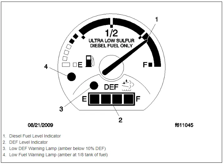
For EPA10-compliant engines or newer, fuel and DEF levels are shown on a combined fuel/DEF gauge (see Fig. 6.10). The diesel fuel level is displayed at the top, with a low-level warning lamp activating at 1/8th tank capacity. Standard vehicles have one fuel gauge; those equipped optionally show each tank's level separately.
The DEF level is indicated in the lower part of the gauge. A low DEF warning lamp illuminates when the DEF capacity drops to 10%. For more on DEF gauge functions, see Chapter 8.
- Diesel Fuel Level Indicator
- DEF Level Indicator
- Low DEF Warning Lamp (amber under 10% DEF)
- Low Fuel Warning Lamp (amber at 1/8 tank of fuel)
Primary and Secondary Air Pressure Gauges
Warning: Low air pressure significantly reduces braking capability. Slow down and stop the vehicle safely. Wait to drive until air pressure is above the minimum level. Driving with inadequate brakes can lead to accidents, potentially causing damage, injury, or death.
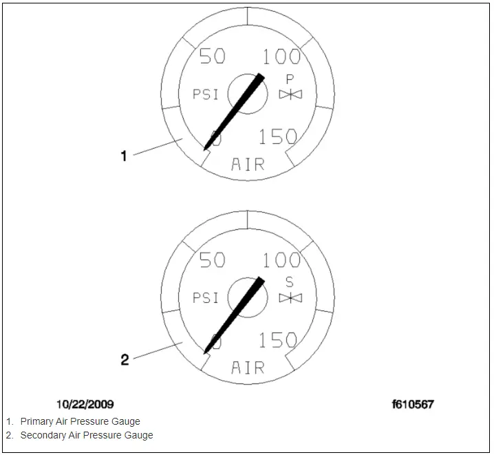
Air pressure gauges display the pressure in the primary and secondary air systems, normally between 100 to 120 psi (690 to 827 kPa) when the engine runs (see Fig. 6.11).
- Primary Air Pressure Gauge
- Secondary Air Pressure Gauge
All vehicles with air brakes must have these gauges. A low-air-pressure warning lamp and buzzer, connected to both systems, activate when pressure drops below 65 to 75 psi (448 to 517 kPa).
Upon starting the engine, the warning lamp and buzzer stay on until both systems exceed the minimum pressure.
Voltmeter
The digital voltmeter, visible on the driver display screen when the ignition is on, shows the vehicle's charging system voltage while running and battery voltage when stopped. Monitoring this helps detect potential charging system issues before the battery discharges, causing startup problems.
Normally, the voltmeter displays about 13.7 to 14.1 volts with the engine running. When the engine is off, a fully charged battery shows 12.7 to 12.8 volts. Voltages below 12.0 volts suggest a low battery, and around 11.0 volts indicate a fully discharged battery. Voltage decreases during startup or when using electrical devices.
Prolonged undercharged or overcharged readings should prompt a system check at a service facility.
Optional Instruments
Optional instruments, not standard on every vehicle, operate independently and are often on the auxiliary dash panel. They are listed alphabetically for easy reference.
Air Intake Restriction Gauge
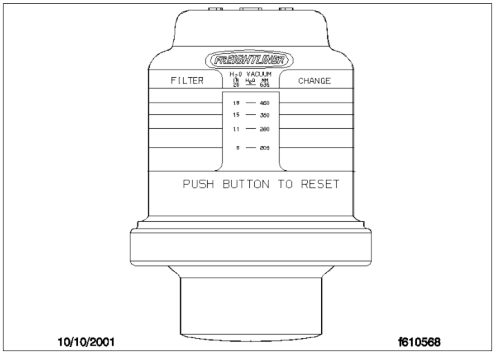
This gauge shows the vacuum on the engine side of the air cleaner, usually mounted on the air intake duct in the engine compartment (see Fig. 6.12). For convenience, it can optionally be placed on the dash, typically on the right-hand control panel.
Measured in inches of water (inH2O), the gauge should be checked with the engine off. If the yellow signal is in the red zone or at or above 25 inH2O after the engine is off, it's time to replace the air cleaner element.
Note: High readings can temporarily occur due to rain or snow wetting the filter.
Ammeter
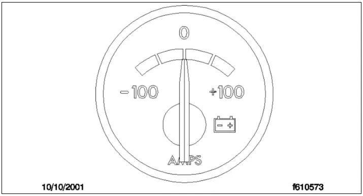
The optional ammeter tracks current to and from the battery (see Fig. 6.13). Charging moves the needle to the plus side while discharging points it to the minus. Consistent negative readings with the engine running could indicate a charging system issue.
Rear Axle Oil Temperature Gauge
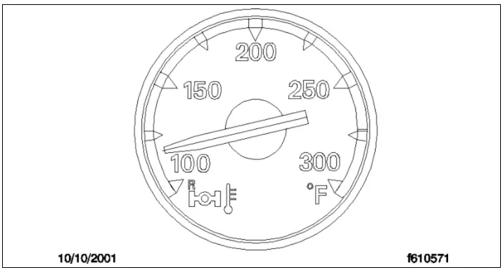
Notice: An unexpected rise in oil temperature, not due to increased load, might signal mechanical failure. Stop safely to investigate and correct the issue before continuing.
Normally, for Detroit™ and Meritor™ drive axles, the rear axle oil temperature gauge should read between 160 and 220°F (71 and 104°C) during standard operation (see Fig. 6.14). Under heavy loads, like steep climbs, temperatures up to 250°F (121°C) are normal.
Digital Clock
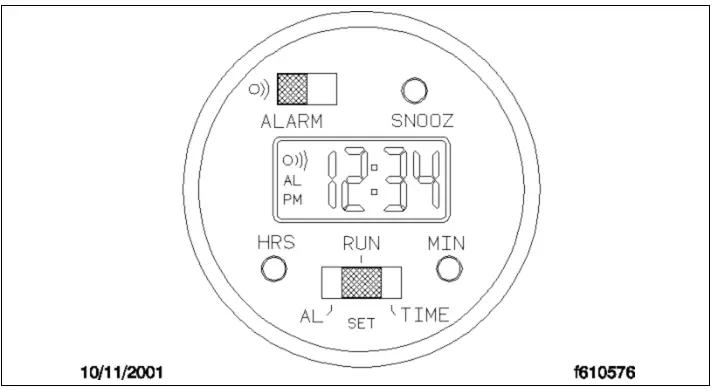
The optional digital clock features black characters on a green display that adjusts brightness for day and night (see Fig. 6.15). It includes a 24-hour alarm with a three-minute snooze feature.
Setting the Time:
- Move the Run/Set switch to TIME-SET.
- Adjust the hour (PM appears for afternoon/evening times).
- Adjust the minute.
- Return the switch to RUN.
Setting the Alarm:
- Switch to ALARM-SET.
- Set the alarm time (AM or PM).
- Return to RUN.
Operating the Alarm:
- Activate the alarm (AL and a symbol appear).
- At the alarm time, it sounds 1 minute unless snoozed or turned off.
- Snooze by pressing SNOOZ; the alarm flashes until it is off or displays for 1 minute.
- Turn off the alarm by moving the switch; the symbol disappears.
Engine Oil Temperature Gauge
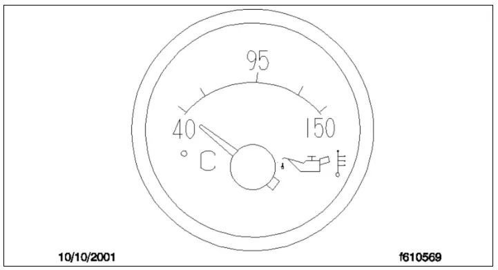
Notice: An unexpected oil temperature increase unrelated to an increased load could indicate a mechanical failure. Safely stop the vehicle to address this issue before continuing operation. The engine should only be used once the cause is identified and fixed.
For Cummins ISB engines, the normal range for the optional engine oil temperature gauge is between 180 to 225°F (82 to 107°C). Note that exceeding this range briefly under heavy loads, like steep inclines, is normal. If the temperature normalizes after the load decreases, there is no concern. Refer to Fig. 6.16.
Pyrometer
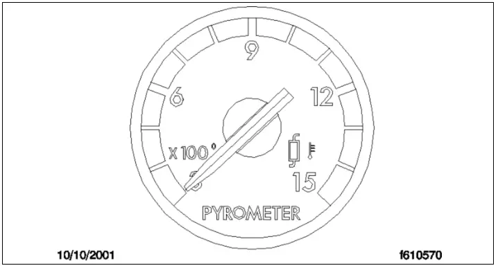
The optional pyrometer, installed on the exhaust pipe, measures exhaust temperatures near the turbocharger (see Fig. 6.17). The maximum safe exhaust temperature for Cummins ISB engines is 1290°F (700°C). Fluctuations in engine load can affect exhaust temperatures. If the pyrometer indicates excessive heat, reduce engine fuel or shift to a lower gear to mitigate engine overload.
Transmission Fluid Temperature Gauge
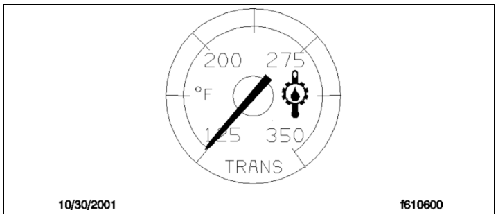
Under normal conditions, the transmission fluid temperature should not exceed 250°F (121°C). See Fig. 6.18 for reference.
Notice: A sudden rise in transmission fluid temperature, not due to increased load, could suggest a mechanical failure. Stop the vehicle safely and investigate the cause before proceeding. The car should remain unused until the issue is resolved. Note that temperatures may rise above this level briefly under heavy loads, like during steep ascents.
Turbocharger Boost Pressure Gauge
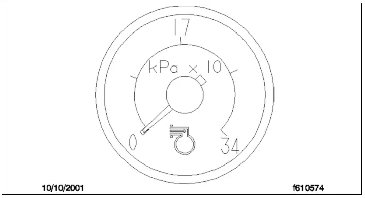
This gauge measures the pressure in the intake manifold created by the turbocharger, which is above atmospheric pressure. See Fig. 6.19 for more details.
Read Also: Forklift Warning Light
What do the Different Colors of Freightliner Dash Symbols Mean?
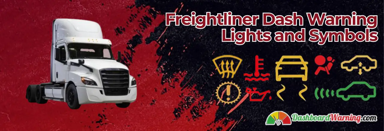
The Freightliner dash warning light symbols are designed to provide the driver with a quick and easy way to identify potential problems with their vehicle. Each character represents a different type of problem, and the severity of the problem is indicated by the color of the symbol.
- Red: A red symbol indicates a severe problem that needs to be addressed immediately. If you see a red mark on your dash, pull over and stop your vehicle as soon as it is safe.
- Yellow: A yellow symbol indicates a potential problem that a qualified Freightliner technician should check out at your earliest convenience. If you see a yellow sign, get your vehicle serviced immediately.
- Green: A green symbol indicates that the system or component the character represents works correctly. Green symbols are used for informational purposes only and do not indicate a problem with your vehicle.
We hope this article has helped you understand the meaning of some of the most common Freightliner dash warning lights and symbols. While it is always best to consult your owner's manual or a qualified technician when dealing with vehicle issues, it is helpful to understand what the different lights and symbols mean. By knowing what the other dash lights and symbols indicate, you can be better prepared to deal with any potential problems that may arise while on the road.
Read Also: Kenworth Dash Warning Lights
FAQs About Freightliner Dash Warning Lights and Symbols
What are the standard dashboard lights and their meanings?
It is essential to be aware of the dashboard lights in a car and understand their meanings. Standard dashboard lights indicate when something is not working correctly or if there is a serious, potentially dangerous problem. Green dashboard lights typically signal that the system is functioning as it should or is currently in use, while yellow indicates that extra care should be taken and an issue may need to be addressed. Red warning lights signify a more serious problem requiring immediate attention - stop driving as soon as possible.
What does a yellow engine light mean on a Freightliner?
When the check engine light begins to flash on a Freightliner, it is essential to pull over and turn off the vehicle as soon as possible. Additional oil or temperature warning lights could indicate more serious issues. It is ill-advised to continue driving with a flashing check engine light, as it could lead to costly damage to the engine components.
What is the red circle on the Freightliner dash?
A low-air warning light illuminates the dashboard of the Freightliner Cascadia. This alert appears when the air pressure within the system decreases to between 60-65 PSI, thus prompting it to come on as an indicator.
What are the two main types of dashboard warning lights?
This dashboard warning light system is designed to alert drivers of potential problems with their cars. If illuminated, a red warning light generally indicates an urgent issue that requires immediate attention. An orange warning light may indicate a less severe problem that will not cause the car to stop working. However, it should still be taken seriously and checked out as soon as possible to maintain the vehicle's safety and reliability.
Was this page helpful?



As a driver, I recognize how important it is to be aware of the warning lights and symbols on my vehicle's dash. This blog post was very helpful in understanding what each Freightliner symbol means and the significance behind them. Knowledge like this is crucial for me to ensure that myself and my load remain safe.